A Guide to Resistance Measurement
With resistance measurement, precision is everything. This guide is what we know about achieving the highest quality measurements possible.
Index
- Introduction to resistance measurement
- Applications
- Resistance
- Principles of resistance measurement
- Methods of 4 terminal connections
- Possible measurement errors
- Choosing the right instrument
- Application examples
- Useful formulas and charts
- Find out more
1. Introduction
The measurement of very large or very small quantities is always difficult, and resistance measurement is no exception. Values above 1GΩ and values below 1Ω both present measurement problems.
Cropico is a world leader in low resistance measurement; we produce a comprehensive range of low resistance ohmmeters and accessories which cover most measurement applications. This handbook gives an overview of low resistance measurement techniques, explains common causes of errors and how to avoid them. We have also included useful tables of wire and cable characteristics, temperature coefficients and various formulas to ensure you make the best possible choice when selecting your measuring instrument and measurement technique. We hope you will find this guide a valuable addition to your toolkit.
2. Applications
Manufacturers of components
Resistors, inductors and chokes all have to verify that their product meets the specified resistance tolerance, end of production line and quality control testing.
Manufacturers of switches, relays & connectors
Verification that the contact resistance is below pre specified limits is required. This can be achieved at end of production line testing, ensuring quality control.
Cable manufacturers
Must measure the resistance of the copper wires they produce, resistance too high means that the current carrying capability of the cable is reduced; resistance too low means that the manufacturer is being too generous on the cable diameter using more copper than he needs to, which can be very expensive.
Installation & maintenance of power cables, switchgear & voltage tap changers
These require the cable joints and switch contacts to be of the lowest possible resistance thus avoiding the joint or contact from becoming excessively hot, a poor cable joint or switch contact will soon fail due to this heating effect. Routine preventative maintenance with regular resistance checks ensures the best possible life performances.
Electric motor & generator manufacturers
There is a requirement to determine the maximum temperature reached under full load. To determine this temperature, the temperature coefficient of the copper winding is used. The resistance is first measured with the motor or generator cold i.e. at ambient temperature, the unit is then run at full load for a specified period and the resistance measured again. From the change in resistance value, the internal motor/generator temperature can be determined. Our ohmmeters are also used to measure the individual coils of a motor winding, to ensure there are no short or open circuit turns and that each coil is balanced.
The automotive industry
Requirement to measure the resistance of robot welding cables to ensure that the weld quality does not deteriorate, i.e. battery lead crimp connectors, air bag detonator resistance, resistance of wiring harness, and quality of crimp connectors on components.
Fuse manufacturers
For quality control, resistance bonding measurements on aircraft and military vehicles, it is necessary to ensure that all equipment installed in aircraft is electrically connected to the air frame, including galley equipment. Tanks and other military vehicles have the same requirements. Producers and users of large electrical currents all need to measure distribution of joint resistance, busbars, and connectors to electrodes for electroplating.
Railway utilities
Including trams and underground railways (Metro) - for the measurement of power distribution cable joints, including the resistance of rail track joints, because the rails are often used for signalling information.
3. Resistance
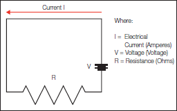
Ohm’s Law V = I x R (Volts = Current x Resistance). The Ohm (Ω) is a unit of electrical resistance equal to that of a conductor in which a current of one ampere is produced by a potential of one volt across its terminals. Ohm's law, named after its discoverer the German physicist Georg Ohm, is one of the most important, basic laws of electricity. It defines the relationship between the three fundamental electrical quantities: current, voltage and resistance. When a voltage is applied to a circuit containing only resistive elements, current flows according to Ohm's Law, which is shown below.
4. Principles of resistance measurement
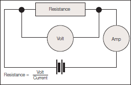
Ammeter Voltmeter method
This method goes right back to basics. If we use a battery as our voltage source, a voltmeter to measure the voltage and an ammeter to measure the current in the circuit, we can calculate the resistance with reasonable accuracy. Whilst this method can provide good measurement results, it is not a practical solution to everyday measurement needs.
Kelvin Double Bridge
The Kelvin Bridge is a variation of the Wheatstone bridge which enables low resistances to be measured. The measurement range would typically be 1mΩ to 1kΩ with the smallest resolution of 1μΩ. The limitations of the Kelvin bridge are:-
- requires manual balancing
- sensitive null detector or galvanometer is required to detect balance condition
- measurement current needs to be reasonably high to achieve sufficient sensitivity
The Kelvin Double Bridge has generally been replaced by digital ohmmeters.
DMM - Two-wire Connection
A simple digital multimeter can be used for higher values of resistance. They employ the 2 wire method of measurement and are only suitable for measuring values above 100Ω and where high accuracy is not required.
When measuring the resistance of a component (Rx) a test current is forced through the component and the test meter measures the voltage at its terminals. The meter then calculates and displays the resulting resistance and is known as a twowire measurement. It should be noted that the meter measures the voltage at its terminals and not across the component. As a result of this, the voltage drop across the connection leads is also included in the resistance calculation. Good quality test leads will have a resistance of approximately 0.02Ω per meter. In addition to the resistance of the leads, the resistance of the lead connection will also be included in the measurement and this can be as high as or even higher in value than the leads themselves.
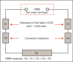
When measuring larger resistance values this additional lead resistance error can be ignored, but as you can see from the chart below, the error becomes significantly higher as the measured value decreases, and totally inappropriate below 10Ω.
TABLE 1
Examples of possible measurement errors
| RX | Test lead resistance R1 + R2 | Connection resistance R3 + R4 | Rx measured at DMM terminals = Rx + R1 + R2 + R3 + R4 | Error | Error % |
| 1000 Ω | 0.04 Ω | 0.04 Ω | 1000.08 Ω | 0.08 Ω | 0.008 |
| 100 Ω | 0.04 Ω | 0.04 Ω | 100.08 Ω | 0.08 Ω | 0.08 |
| 10 Ω | 0.04 Ω | 0.04 Ω | 10.08 Ω | 0.08 Ω | 0.8 |
| 1 Ω | 0.04 Ω | 0.04 Ω | 1.08 Ω | 0.08 Ω | 8 |
| 100 mΩ | 0.04 Ω | 0.04 Ω | 180 mΩ | 0.08 Ω | 80 |
| 10 mΩ | 0.04 Ω | 0.04 Ω | 90 mΩ | 0.08 Ω | 800 |
| 1 mΩ | 0.04 Ω | 0.04 Ω | 81 mΩ | 0.08 Ω | 8000 |
| 100 µΩ | 0.04 Ω | 0.04 Ω | 80.1µΩ | 0.08 Ω | 8000 |
To measure true DC, resistance ohmmeters typically use 4 wire measurement. DC current is passed through the Rx and through the ohmmeter’s internal standard. The voltage across the Rx and the internal standard is then measured and the ratio of the two readings is used to calculate the resistance. With this method the current only needs to be steady for the few milliseconds required for the ohmmeter to make both readings, but it requires two measurement circuits. The voltage measured is very small and a μV measurement sensitivity is usually required.
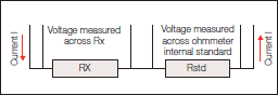
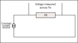
Alternatively a constant current source is used to pass a current through the Rx. The volt drop across the Rx is then measured and the resistance calculated. This method requires only one measurement circuit but the current generator has to be stable under all measurement conditions.
Four wire connection
The four wire (Kelvin) method of measurement is preferred for resistance values below 100Ω, and all Seaward milliohmmeters and microhmmeters use this method. These measurements are made using 4 separate wires. 2 wires carry the current, known as the source or current leads and pass current through the Rx. The other 2 wires known as the sense or potential leads, are used to sense the voltage drop across Rx. Whilst some small current will flow in the sense leads, it is negligible and can be ignored. The volt drop across the ohmmeter’s sense terminals is therefore virtually the same as the volt drop across Rx. This method of measurement will produce accurate and consistent results when measuring resistances below 100Ω.
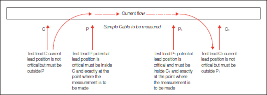
From a measurement point of view this is the best type of connection with 4 separate wires; 2 current (C and C1) and 2 potential (P and P1). The current wires must always be placed outside the potential although the exact placement is not critical. The potential wires must be connected exactly at the points you want to measure between. The measured value will be between the potential points. Whilst this gives the best measurement results it is often not practical. We live in a non perfect world and sometimes small compromises have to be made, Cropico can offer a number of practical measurement solutions.
5. Methods of 4 terminal connections
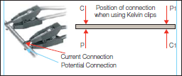
Kelvin clips
Kelvin clips are similar to crocodile (Alligator) clips but with each jaw insulated from the other. The current lead is connected to one jaw and the potential lead to the other. Kelvin clips offer a very practical solution to making a four terminal connection to wires, busbars, plates etc.
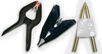
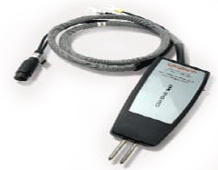
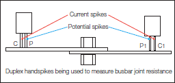
Duplex Handspikes
Handspikes offer another very practical connection solution particularly for sheet material, busbars and where access can be a problem. The handspike consists of two sprung spikes enclosed in a handle. One spike is the current connection and the other is the potential or sense connection.
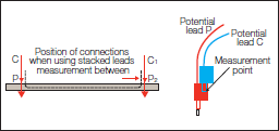
Stacked Lead connection
Sometimes the only practical solution to making a connection to the Rx is to use stacking leads. The current lead is pushed into the back of the potential lead. This method will give small errors because the measurement point will be where the potential lead connects to the current lead. For measurement of awkward-to-reach samples, this can be the best compromise solution.
Cable clamps
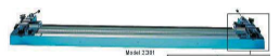
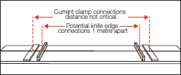
When measuring cables during manufacture, and for quality control purposes, it is necessary to maintain consistent measuring conditions. The length of the cable sample is normally 1 metre and to ensure that accurate 1 metre lengths are measured, a cable clamp should be used. Cropico offer a variety of cable clamps which will accommodate most cable sizes. The cable to be measured is placed in the clamp and the ends of the cable are clamped in the current terminals. The potential connection points are normally in the form of knife edge contacts which are exactly 1 metre apart.
Jigs and fixtures
When measuring other components such as resistors, fuses, switch contacts, rivets etc. the importance of using a test jig to hold the component cannot be emphasised enough. This will ensure that the measurement conditions, i.e. position of measurement leads, are the same for each component which will result in consistent, reliable and meaningful measurements. Jigs often have to be specially designed to suit the application.
6. Possible measurement errors
There are several possible sources of measurement error associated with low resistance measurements. The most common ones are described below.
Dirty connections
As with all measurements, it is important to ensure that the device you are connecting is clean and free from oxides and dirt. High resistance connections will cause reading errors and may prevent measurements. It should also be noted that some coatings and oxides on materials are good insulators. Anodising has a very high resistance and is a classic example. Be sure to clean off the coating at the connection points. Cropico ohmmeters incorporate a lead error warning which will indicate if the connections are too high in resistance.
Resistance of leads too high
Whilst in theory the four terminal method of measurement is unaffected by lead length, care must be taken to ensure that the leads are not too high in resistance. The potential leads are not critical and can usually be up to 1kΩ without affecting the measurement accuracy, but the current leads are critical. If the current leads are too high in resistance then the voltage drop across them will result in insufficient voltage across the DUT (Device Under Test) to make a sensible reading. Cropico ohmmeters check this compliance voltage across the DUT and prevent a measurement from being made if it falls too low. A warning display is also provided; preventing the reading, ensuring that false measurements are not carried out. If you need to use long measuring leads, then increase the diameter of the cables to reduce their resistance.
Measurement Noise
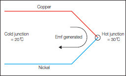
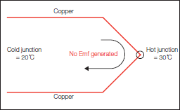
As with any type of low voltage measurement, noise can be a problem. Noise is created within test leads when they are in the influence of a magnetic field which is changing or the leads are moving within that field. To minimise this effect, leads should be kept as short as is practical, kept still and ideally shielded. Cropico realises that there are many practical constraints on achieving this ideal, and have therefore designed the circuits within their ohmmeters to minimise and eliminate these effects. Thermal emf Thermal emf in the DUT is probably the biggest cause of errors in low resistance measurements. We must first understand what we mean by thermal emf, and how it is generated. Thermal emfs are small voltages which are generated when two dissimilar metals are joined together, forming what is known as a thermocouple junction. A thermocouple will generate an emf depending upon the materials used at the junction and the temperature difference between the hot and the reference, or cold, junction.
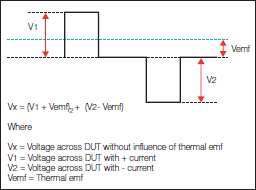
This thermocouple effect will introduce errors into the measurement if steps are not taken to compensate and eliminate these thermal emfs. Cropico microhmmeters and milliohmmeters eliminate this effect by offering an automatic average mode for the measurement, sometimes called the switched DC or average method. A measurement is made with the current flowing in the forward direction then a second measurement is made with the current in the reverse direction. The value displayed is the average of these two measurements. Any thermal emf in the measuring system will add to the first measurement and be subtracted from the second; the resulting average value displayed eliminates or cancels the thermal emf from the measurement. This method gives the best results for resistive loads but is not suitable for inductive samples such as motor or transformer windings. In these cases the ohmmeter is likely to switch current direction before the inductance is fully saturated and the correct measured value will not be achieved.
Measurement of joint resistance of 2 busbars
Wrong Test Current
Consideration should always be given to the effect the measurement current will have on the DUT. Devices with a small mass or constructed with materials that have a high temperature coefficient, such as thin strands of copper wire, will need to be measured with the minimum current available to avoid heating. In these cases a single pulse of current may be appropriate to cause the very minimum of heating. Should the DUT be subject to the influences of thermal emf then the switched current method described earlier is appropriate. The Cropico DO5000 series of ohmmeters have selectable currents from 10% to 100% in 1% steps, plus a single pulse mode and consequently may be configured to suit most applications.
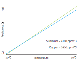
Temperature influences
It is important to be aware that the resistance of most materials will be affected by their temperature. It may be necessary, depending upon the accuracy of measurement required, to control the environment in which the measurement is made, thus keeping the ambient temperature constant. This would be the case when measuring resistance reference standards which are measured in a controlled laboratory at either 20°C or 23°C. For measurements where controlling the ambient temperature is not possible, the ATC (automatic temperature compensation) facility can be used. A temperature probe, connected to the ohmmeter, senses the ambient temperature and the resistance reading is corrected to a reference temperature of 20°C. Two of the most common materials measured are copper and aluminium and their temperature coefficients are illustrated opposite.
The Temperature Coefficient of Copper (near room temperature) is +0.393 % per °C. This means if the temperature increases 1°C the resistance will increase 0.393%. Aluminium is +0.4100 % per °C.
7. Choosing the right instrument
TABLE 2
Typical Instrument specification chart
| Range | Resolution | Measurement Current | Accuracy @ 20 o C ±5 o C, 1 year | Temperature Coefficient / o C |
| 60 Ω | 10 mΩ | 1 mA | ±(0.15% Rdg + 0.05% FS) | 40 ppm Rdg + 30 ppm FS |
| 6 Ω | 1 mΩ | 10 mA | ±(0.15% Rdg + 0.05% FS) | 40 ppm Rdg + 30 ppm FS |
| 600 mΩ | 100 µΩ | 100 mA | ±(0.15% Rdg + 0.05% FS) | 40 ppm Rdg + 30 ppm FS |
| 60 mΩ | 10 µΩ | 1A | ±(0.15% Rdg + 0.05% FS) | 40 ppm Rdg + 30 ppm FS |
| 6 mΩ | 1 µΩ | 10A | ±(0.2% Rdg + 0.01% FS) | 40 ppm Rdg + 30 ppm FS |
| 600 µΩ | 0.1 µΩ | 10A | ±(0.2% Rdg + 0.01% FS) | 40 ppm Rdg + 250 ppm FS |
Range:
The maximum reading possible at that setting
Resolution:
The smallest number (digit) displayed for that range
Measurement Current:
The nominal current used by that range
Accuracy:
Uncertainty of the measurement over the ambient temperature range 15 to 25°C
Temperature Coefficient:
The additional possible error below ambient temperature of 15°C and above 25°C
When selecting the best instrument for your application the following should be taken into consideration:-
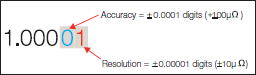
Accuracy can be better described as the uncertainty of measurement, which is the closeness of the agreement between the result of a measured value and the true value. It is normally expressed in two parts i.e. a percentage of reading plus a percentage full scale. The accuracy statement should include the temperature range applicable, plus the length of time the accuracy will remain within the indicated limits. Warning: some manufacturers give a very high accuracy statement but this is valid only for a short period of 30 or 90 Days. All Cropico ohmmeters specify accuracy for a full 1 year.
Resolution is the smallest increment that the measuring instrument will display. It should be noted that to achieve high measurement accuracy a suitably high resolution is needed, but a high resolution in itself does not indicate that the measurement has a high accuracy.
Example: To measure 1Ω with an accuracy of 0.01% (± 0.0001) requires the measurement to be displayed with a minimum resolution of 100μΩ (1.0001ohms).
A measured value can also be displayed with a very high resolution but low accuracy i.e. 1Ω measured to an accuracy of 1% but a resolution of 100μΩ would be displayed as 1.0001Ω. The only meaningful digits would be 1.0100, the last two digits only showing the fluctuations in the measured values. These fluctuations can be misleading and emphasising any instability of the DUT. A suitable resolution should be selected to ensure a comfortable reading of the display.
Measurement Scale length
Digital measuring instruments display the measured value with displays that have a maximum count, often 1999 (sometimes referred to as 3Ω digit). This means that the maximum value that can be displayed is 1999 and the smallest resolution is 1 digit in 1999. For a measurement of 1Ω the display will read 1.000, a resolution of 0.001mΩ. If we wish to measure 2Ω we will need to select a higher range 19.99Ω full scale and the value will be displayed as 2.00Ω, a resolution of 0.01Ω. You can therefore see that it is desirable to have a longer scale length than the traditional 1999. The Cropico ohmmeters offer scale lengths up to 6000 count, which would give a displayed value of 2.000, with a resolution of 0.001Ω.
Range Selection
Range selection can be either manual or automatic. Whilst automatic range selection can be very useful when the value of Rx is unknown, the measurement takes longer as the instrument needs to find the correct range. For measurements on a number of similar samples, it is better to manually select the range. In addition to this, the various instrument ranges will measure with different currents which may not be suitable for the device being tested. When measuring inductive samples, such as motors or transformers, the measured value rises as the inductance is saturated until the final value is reached. Automatic range selection should not be used in these applications, as by changing ranges the measuring current is interrupted and its magnitude may also be changed and a final steady reading is unlikely to be achieved.
| Scale Length | 1.999 | 19.99 | 2.000 | 20.00 | 3.000 | 30.00 | 4.000 | 40.000 | |
| Display Reading | |||||||||
| Measured Values | 1.000 | 1.000 | 1.000 | 1.000 | 1.000 | ||||
| 2.000 | Range up | 2.00 | 2.000 | 2.000 | 2.000 | ||||
| 3.000 | Range up | 3.00 | Range up | 3.00 | 3.000 | 3.000 | |||
| 4.000 | Range up | 4.00 | Range up | 4.00 | Range up | 4.00 | 4.000 | ||
Temperature coefficient
The temperature coefficient of a measuring instrument is important as it can significantly affect the accuracy of the measurement. Measuring instruments are normally calibrated in an ambient temperature of 20 or 23°. The temperature coefficient states how the measured accuracy is affected due to variations in ambient temperature.
Current Magnitude and Mode
Selecting an instrument with the appropriate measuring current for the application is important. For example, if thin wires are to be measured, then a high measuring current would heat the wire and change its resistance value. Copper wire has a temperature coefficient of 4% per °C at ambient temperatures, so for a wire with a 1Ω resistance, raising the temperature by 10°C will increase its value to 10 x 0.004 = 0.04Ω. Some applications, however, benefit from higher currents.
The measurement current mode can also be important. Again, when measuring thin wires, a short measurement pulse of current rather than using a continuous current, will minimise any heating effect. A switched DC measuring mode may also be appropriate to eliminate thermal emf errors, but for measuring motor windings or transformers, a current pulse or switched DC would be inappropriate. Continuous current is required to saturate inductance giving the correct measured value. Automatic Temperature Compensation When measuring materials with a high temperature coefficient, such as copper, the resistance value will increase with temperature. Measurements taken at an ambient temperature of 20°C will be 0.4% lower than measurements at 30°C. This can be misleading when trying to compare the values for quality control purposes. To overcome this, some ohmmeters are provided with automatic temperature compensation (ATC). The ambient temperature is measured with a temperature sensor, and the resistance value displayed is corrected for temperature changes referencing the readings to 20°C.
Measurement speed
The speed of measurement is not normally too important and most ohmmeters will measure at approximately 1 reading per second, but in automated processes such as component selection and production line testing, fast measuring speeds, up to 50 measurements per second, can be desirable. Of course when measuring at these speeds the ohmmeter needs to be remotely controlled using a computer or PLC interfaces.
Remote connections
For remote connection IEEE-488, RS232 or PLC interface may be appropriate. The IEEE-488 interface is a parallel port for the transmission of 8 bits (1byte) of information at a time over 8 wires. It has a transmission speed greater than RS232 but is limited in connection cable distance to 20 metres.
The RS232 interface is a serial port for transmission of data in serial bit format. RS232 has a slower transmission speed than IEEE-488 and requires only 3 lines to transmit data, receive data and signal ground.
The PLC interface allows basic remote control of the microhmmeter by a Programmable Logic Controller or similar device.
Environmental
Consideration should be given to the type of environment in which the ohmmeter is to be used. Is a portable unit needed? Does the construction need to be rugged enough to withstand building site conditions? What temperature and humidity range does it need to operate in?
View the Millohmmeters and Microhmmeters product ranges for more information about our products.
Download the full PDF guide which contains all the chapters:
CLICK HERE TO DOWNLOAD THE FULL GUIDE


Sign up to our Newsletter.
Stay up to date with the latest industry and product news, as well as our free educational content such as webinars and our expert guides.
Close