Introduction
Whilst the use of test limits may sound fairly obvious to many, there are some intricacies that should be considered. This article explores the different uses for test limits, how to apply them and where they can be used for not only safety implications but also quality assurance purposes.
Test Limits
Before discussing the different applications for limits, let’s discuss the two types of limits that can be utilised when performing electrical safety testing.
Upper Limits – Setting an upper (or high) limit for the test will ensure the result is deemed a failure should the measured characteristic creep above the defined limit. Any reading beneath the limit is therefore deemed good and a PASS condition will be issued by the test equipment.
The example below shows the application of an upper limit on a Hipot Test
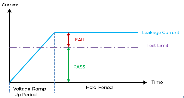
Diagram 1: Upper Limit – Measured current higher than Limit = Test FAIL
Lower Limits – Directly converse to the above, setting a lower limit will issue a failure condition if the measured value falls beneath the limit level.
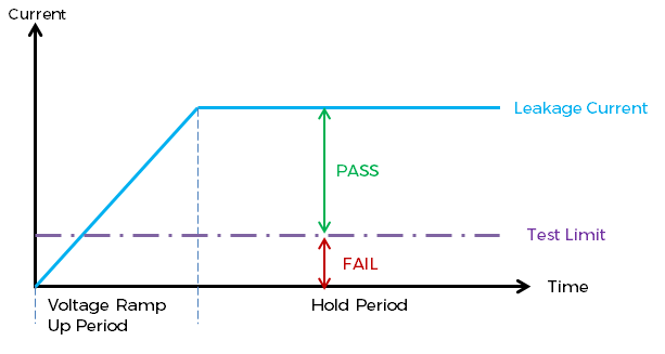
Diagram 2: Lower Limit – Measured current above the lower limit = Test Passed
It is typical that only the limit required for user safety is specified within International compliance documentation. This limit is usually only the mximum or minimum value, dependant upon the test being performed. Let’s take a look at a typical electrical standard to highlight the stated limits and how these should be applied.
In this example we are referencing the test limits as stated for tests complying to EN60598-1 Annex Q, for production (routine) testing of Luminaires
|
Test Type |
Recommended Limit |
Limit Type |
|
Earth Bond |
Maximum Resistance of 0.5Ω |
Upper Limit |
|
Insulation Resistance |
Minimum Resistance of 2MΩ |
Lower Limit |
|
Electric Strength (Hipot) |
Maximum breakdown current 5mA |
Upper Limit |
In terms of compliance it could be argued that provided limits have been set in line with the above, that providing a pass condition is met the test is complete and good. However this does not provide the entire picture, and there are instances where the test may not have been successfully performed. By making one simple change and setting both an upper and lower limit can have multiple benefits for the testing procedure, and can offer peace of mind that the test has been carried out correctly.
Applying both an upper and lower limit creates an effective window inside which the test measurement must sit to be deemed to be good, as can be seen in the diagram below.
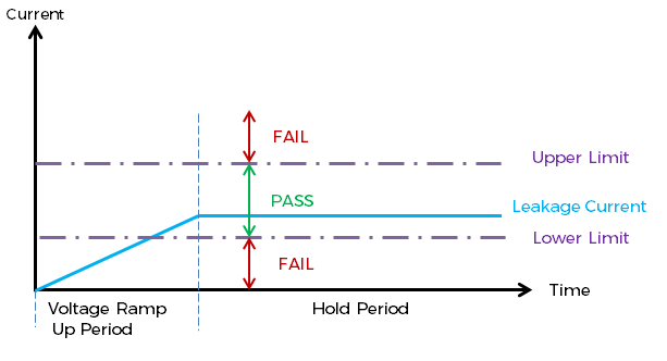
Diagram 3: Application of both Upper and Lower Limits
Using Test Limits as a Check against the test procedure
When a test is performed there are a number of factors that could influence the reading; are connections being properly made? Is the device under test in the correct state for testing? e.g, for certain tests switches may need to be placed into the ON position to ensure full testing of the circuit.
If these conditions are not met, it is possible the test meter could measure a low value or even zero, when a value higher than this is expected. Unless operators are specifically trained to look for this scenario and understand that the unit will need testing, the incorrect Pass condition that would then be issued would not be picked up and potentially hazardous equipment, due to ineffective testing, could be shipped to customers.
Using both an upper and lower limit in this scenario could capture these circumstances and correctly fail a piece of equipment being incorrectly tested.
Application Example – AC Hipot Testing
During an AC Hipot test it is normal to see a small current flowing through the DUT, providing this current does not exceed the Upper limit it is deemed safe. This small current is often due to capacitance within the test circuit, rather than actual breakdown current, nonetheless it is present during the test, and should be consistent across all products of the same type (the same model number).
However should there be a break in the test circuit due to poor placement of test probes or incorrect connections (including the mains power switch not being in the on position), the test will no longer be valid. The measured test current will no longer include this “normal” amount of leakage. By applying a lower limit to the test, any instance where connections have been applied incorrectly will be highlighted, and the test failed alerting the operator to a potential issue with the test method.
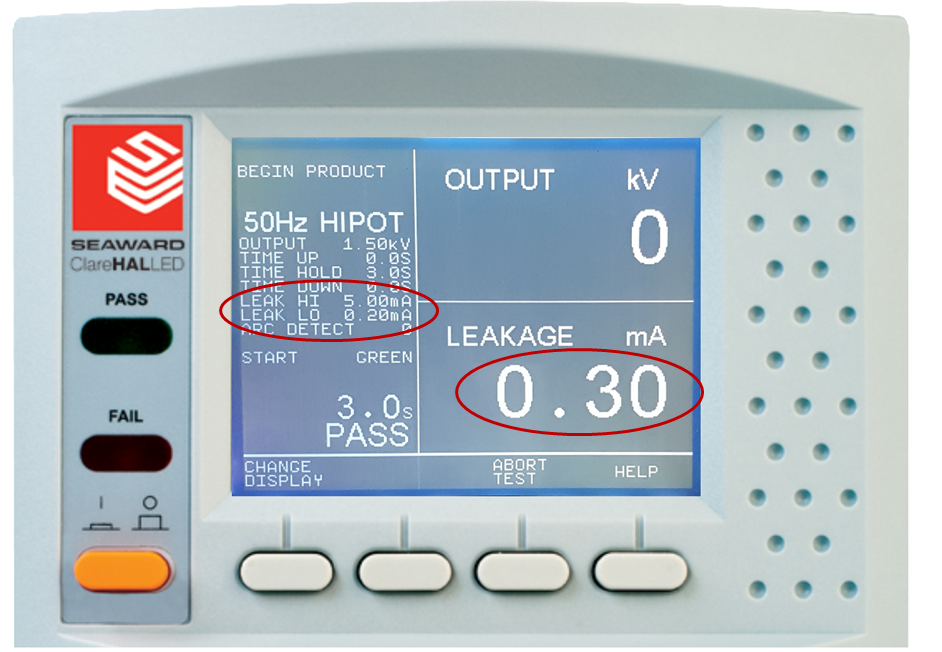 Image 1: Measured Value within Limits - Test PASS
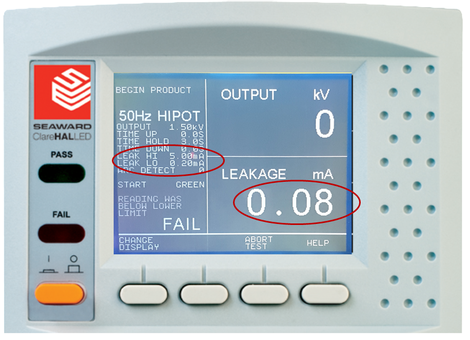 Image 2: Measured Value beneath Lower Test Limit - Test Fail
Using Test Limits as a Quality Measure
If we consider any product always manufactured using the same materials, by a uniform procedure for build, in the same environment, we should reasonably expect to see the same test results for every product manufactured. Therefore for a particular product range an upper and lower limit could be applied to create an acceptable “band” between which good products should fall when tested.
Application Example – Powered Load Test
Consider a manufacturer who makes multiple LED lighting, a component as simple as a resistor with a known value fitted could be the difference between different power consumption ratings across product models. By setting an upper and lower tolerance for the expected power consumption, the production manager can be satisfied that the products passing through the production line are being fitted with the correct components and are meeting company specification.
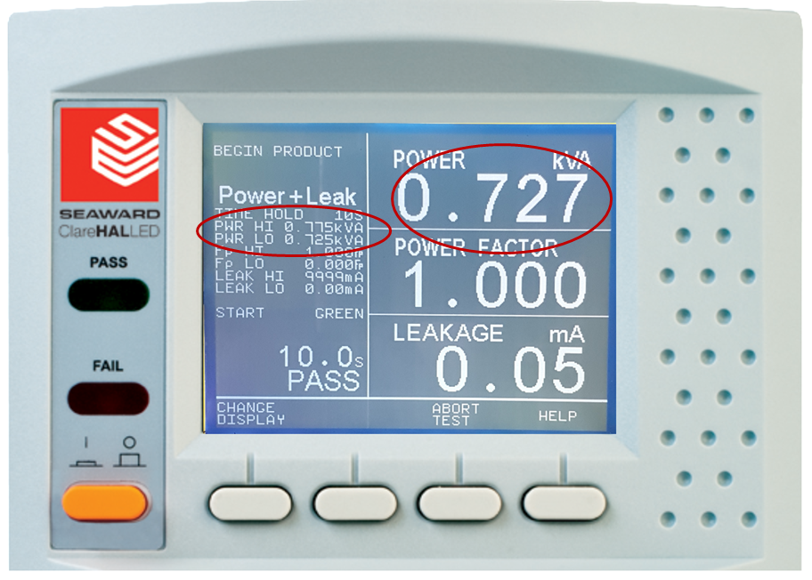
Image 3: Power Test - Measured value within set limits
Using Test Limits as a Check of the Instrument
In certain circumstances setting limits may also prove useful to check that the test equipment is performing properly.
Application Example –Earth Bond Testing
For any bond test performed on a production line we should be expecting to see some resistance, typically in the milliohm range, but what if our tester developed a fault where the reading was zero.
Without a lower limit the test could be deemed as a Pass, but theoretically a zero resistance would be near impossible on any piece of equipment that involves any amount of Earth cable. Applying even a small lower limit to the test parameters would ensure this situation is avoided, as the test would always indicate a failure for any reading beneath the lower limit, and stop any false good items from leaving the factory.
This holds particular importance when we consider the order of tests, as it is typical in a Class 1 (Earthed) product that the Earth bond is followed by a Hipot test. In this situation the earth connection is typically used as a return for the leakage current during the Hipot test, and therefore if we cannot be sure the Earth test was performed correctly we cannot be sure that the connections for the Hipot test are sound and that the insulation is of sufficient strength.
Conclusion
Whilst often underutilised, I hope it can be seen that the application of both upper and lower limits on certain tests can have huge advantages for the test process. These parameters can aid in everything from identifying poor practices and potential training opportunities to possible changes in supplied components. The positives of applying these limits are not countered with negatives; this production test improvement can only improve quality, and confidence in the test it adds none of the precious commodity of time to the testing procedure.
Are you looking for a new Production Line Tester? View our best-selling HAL Series, incorportating the limits discussed in our article, among many other features designed specifically to aid manufacturers like you to ensure fast, efficient and safe production line testing.


Sign up to our Newsletter.
Stay up to date with the latest industry and product news, as well as our free educational content such as webinars and our expert guides.
Close